6502 Video Adapter
You can access the design files for this project here
In Fall 2023, I took the CMU student-taught course Build Your Own Breadboard Computer (which I’m actually teaching starting Fall 2025!). The final project for the course consists of "make your computer do something interesting" - it’s extremely broad, so what I decided to do was give my computer a video output.
The course itself is heavily inspired by Ben Eater’s 6502 series, so it was only reasonable to take inspiration for my video adapter from his "World’s Worst Video Card" series. My design fixes a lot of the problems with Ben’s design, and also makes some general improvements:
-
better timing compliance (shorter critical path → no vertical artifacts)
-
FFs instead of latches (easier to debug timing)
-
higher resolution (160x120 vs. 100x75), accomplished through memory banking
-
more common VGA mode (640x480 vs. 800x600)
-
double-bufferring (updates aren’t restricted to blanking period)
-
software blanking (show solid black or white without drawing to every pixel)
-
configurability (disable NMI if not needed)
Design
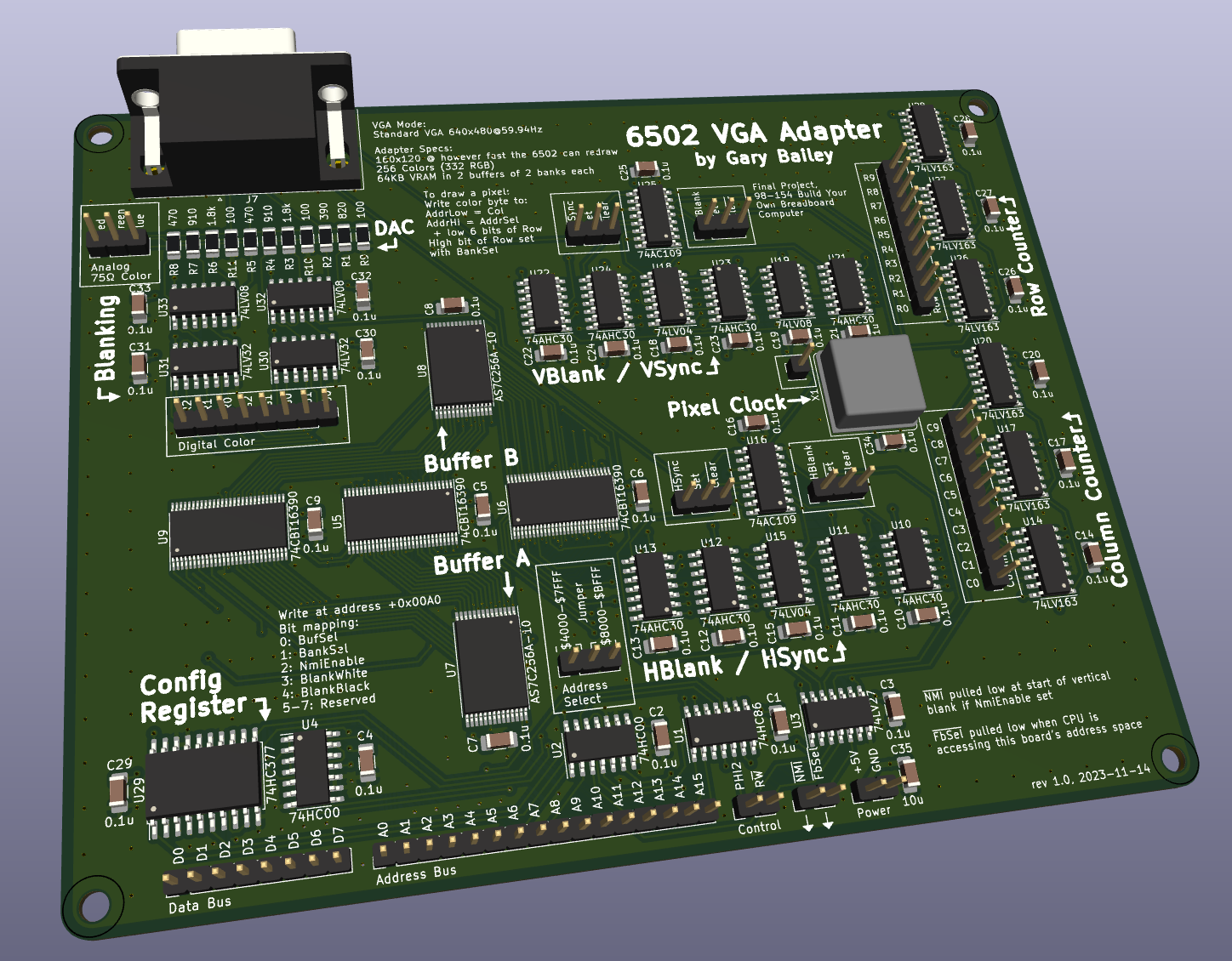
The architecture of the video adapter is pretty simple as far as video drivers go. It only consists of a framebuffer - each pixel on the screen maps to a byte in VRAM. As for the logic design, it’s divided into a few parts: the counters, the sync generation, the memory interface, and the DAC.
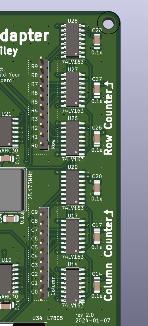
Counters
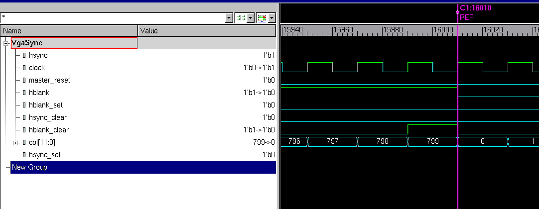
The counters consist of a set of six 4-bit counter ICs arranged into two 12-bit counters for the rows and the columns. They’re 12 bits each because they count the pixels at the VGA mode level: including the blanking periods, that’s 800x525. I only need 10 bits for each of these, but counters come 4 bits at a time…
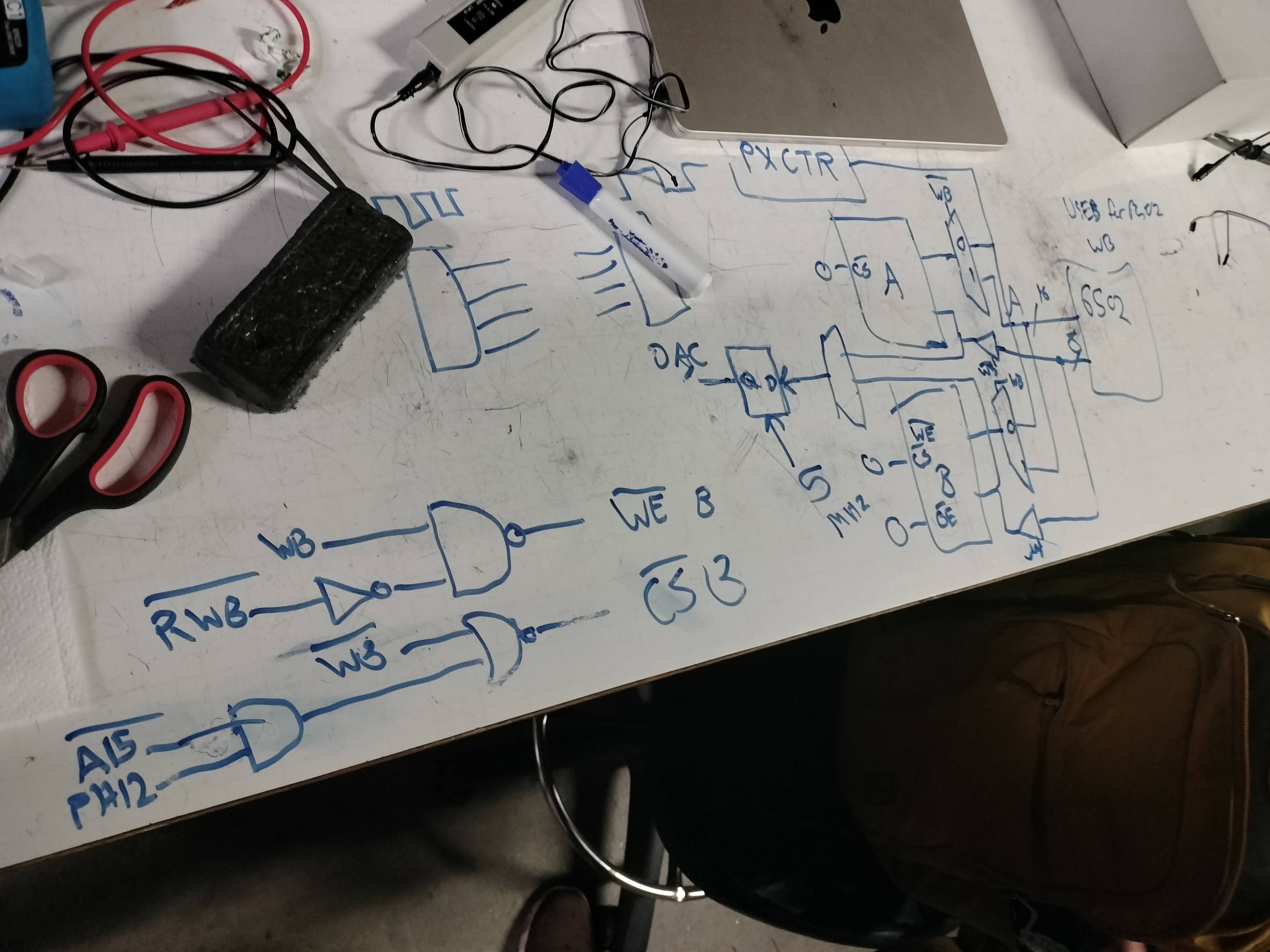
One thing I did to fix the timing issues with Ben Eater’s video card was to try to use flipflops instead of latches for everything (it makes proving the timing compliance of everything easier). Because of this, everything on the board except for the 6502 interface is in a single clock domain driven by the pixel clock, and the logic of counting is controlled by enable and clear inputs instead of gating the clock and resetting asynchronously. The column counter is always enabled, and its clear and the row counter’s enable and clear are controlled by the sync generation.
Sync generation
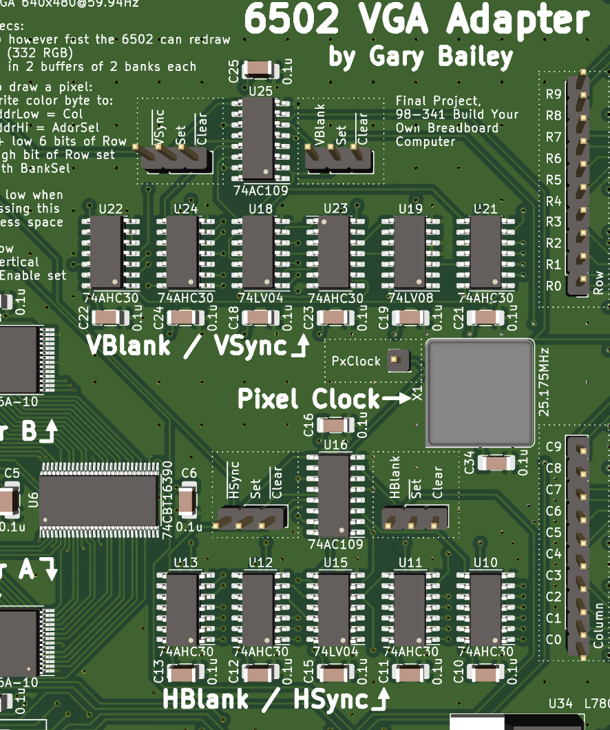
This part is responsible for generating the pulses which communicate to the display where lines and frames begin and end. It consists of four J/K flipflops (one each for [horizontal, vertical] x [blank, sync]), whose J and K inputs are connected to various blobs of combinational logic to start and stop these periods at certain row or column numbers, following the numbers given here. There’s also another set of combinational blobs that clears the column counter (and increments the row by enabling it) after a certain value, and clears the row counter at the end of the frame.
Memory interface
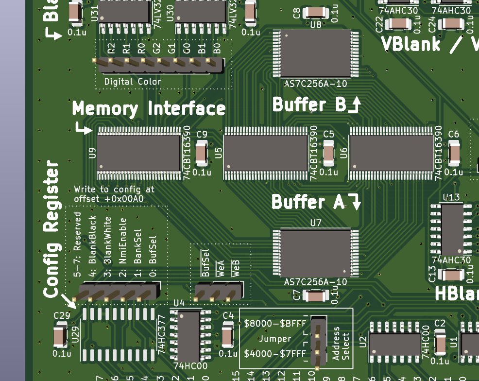
I think the biggest limitation with Ben Eater’s design is that it only allows writing to the VRAM during the blanking period, because the rest of the time the video adapter needs to read from it. I solved this using double-bufferring: there are two separate VRAM chips (which I call the "buffers"), one of which is attached to the computer’s memory bus for drawing, and the other is attached to the row and column counter for displaying. Then, once the computer is done drawing a new frame, the buffers are swapped and the newly drawn buffer is read from and displayed to the screen. The swapping in this case is done by a set of three 74CBT16390 "bus switches", which are pretty much just giant, bidirectional multiplexers.
The row and column are turned into an address by basically just doing addr =
{row[8:2], col[9:2]} - since the lower 2 bits are skipped, it divides the
"native" VGA resolution by 4 to get 160x120.
Also attached to the memory bus is the control register. This is necessary for controlling the buffer swap, but also for another reason: the address space the board gets is not large enough to address all of its VRAM! Due to limitations of the 6502, I can’t give the card the complete 15-bit address space it needs, just 14 bits. To work around this there’s another bit in the control register to set the high bit of the VRAM address being accessed by the computer (this is like a typical "bank switch" control). While the card needs this much address space in order to do its row/column addressing nicely, there’s a lot of unused space within it (each row is given 256 bytes of address space, but they’re only 160 pixels long). This lets me implement the control register by just checking if the computer is writing to the first byte past the end of a row, piggybacking off of my existing address decoding.
DAC
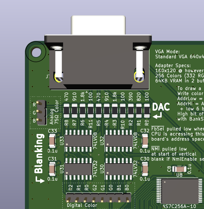
This is the simplest part: it just takes the pixel value and converts it into an analog red, green, and blue color value. Since each pixel is just a byte, it’s divided unevenly into 3 bits for red, 3 bits for green, and 2 bits for blue. The DAC itself is just a simple resistor ladder, but there’s also some circuitry to blank out the signal to 0 during the blanking periods, and since that’s there, I made it so you could blank the screen black or white using a couple bits in the control register.
Design + debugging process
I started off by sketching out rough datapath plans on a whiteboard… I have a couple images of these earlier designs, but of course a lot of things changed between that and the final version.
Then, I took these designs and put them into KiCad. This involved finding actual components for doing the tasks I needed, so were a lot of changes made in this stage.
There were a few weeks of iteration upon this design, then I worked with my friend Salix to build a Verilog model of the design in order to verify that it outputs valid VGA in simulation. This started as a normal RTL design, but then I added gate-level timing in order to ensure my timing requirements were being upheld.
After I was satisfied that the simulation showed that the board would work, I began work on the actual PCB layout. I was pretty addicted to this project at this point so this somehow only took around 10 days to finish, and then the first revision board was ordered.
First revision
Turns out I made a big oopsie on this first revision…
The SRAMs I used, the AS7C256, have two completely different pinouts depending on the package you use, even though both of those packages have basically the same set of pins. I didn’t realize this, so I had naïvely grabbed the built-in KiCad symbol for the DIP version (the TSOP version was not in the libraries) and then applied it to the TSOP package. The result was that pretty much none of the pins were in the right places, to the extent that this board was pretty much a total loss…
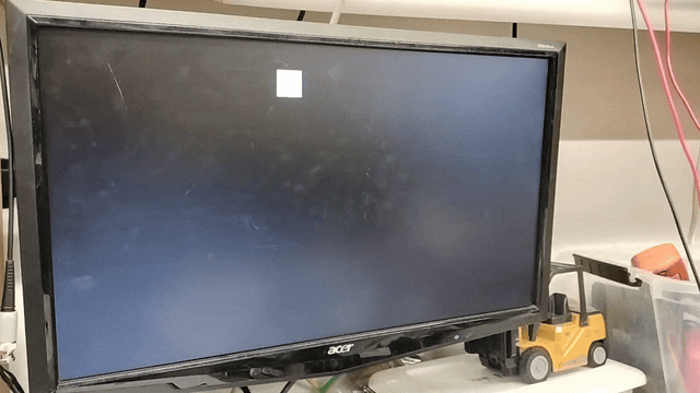
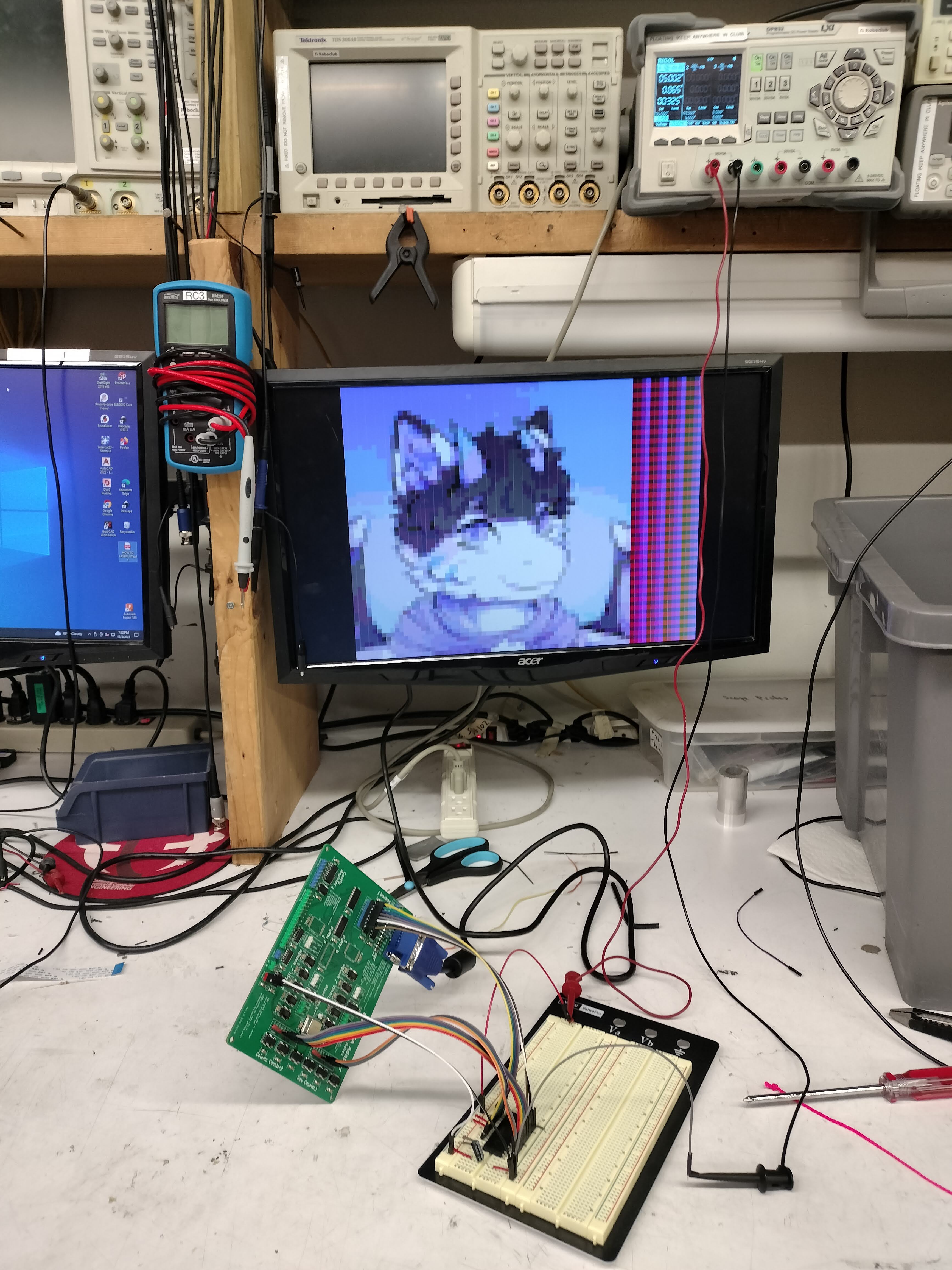
However, not all hope was lost! I just removed the messed up SRAMs and made use of my debug headers to jank together a version that just reads its image from an EEPROM, and that allowed me to show that the video generation works. It has pretty bad vertical artifacting, but that’s due to the EEPROM having very slow access speed compared to the SRAM I specc’d out.
This gave me a load more motivation to do a revision 2, so I got started on that right away.
Second revision
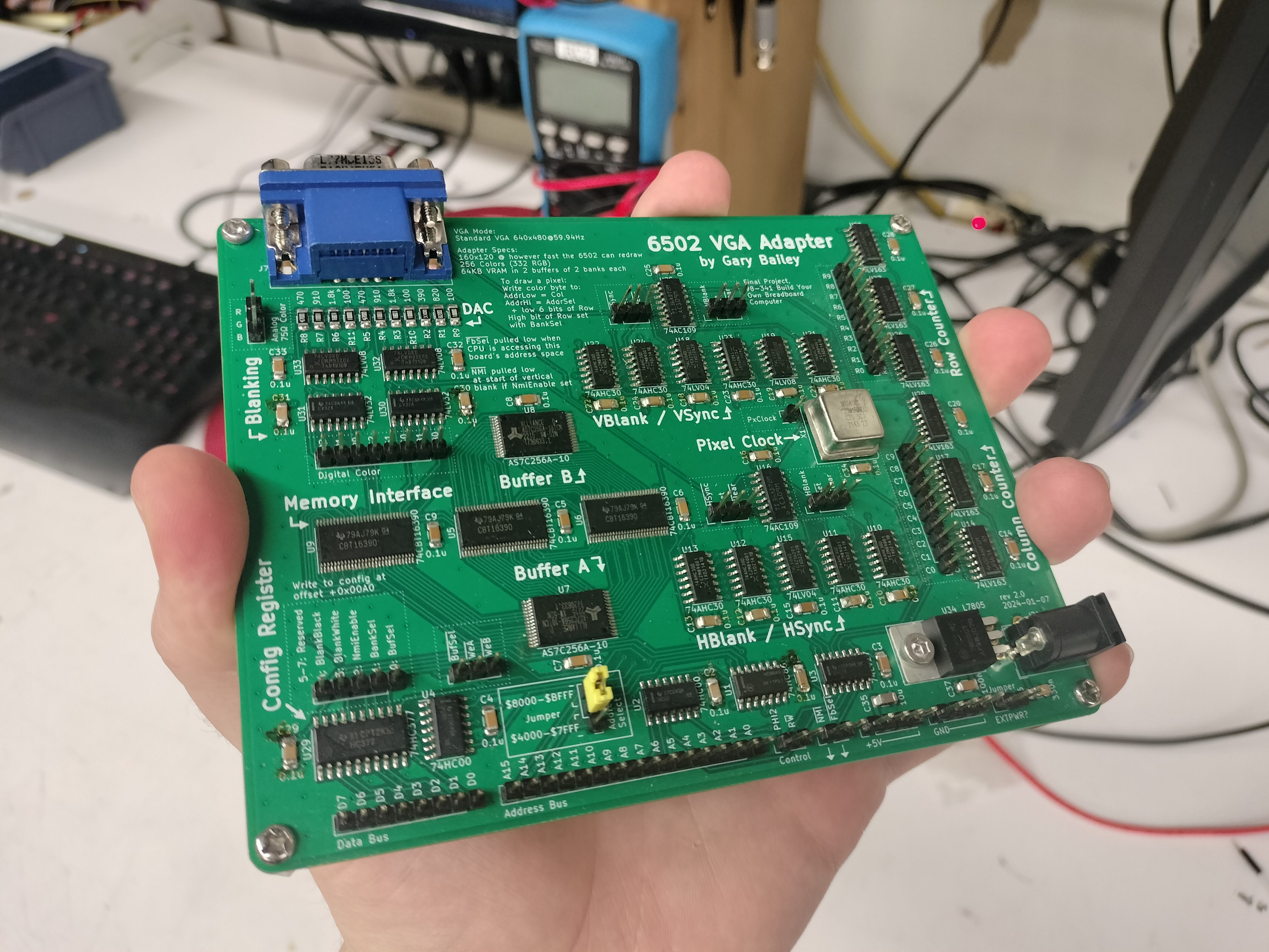
There were 2 big changes from the first revision: the first one is obviously fixing the incorrect SRAM pinout, but the other one was increasing my via size so that I wouldn’t be upcharged $40. It turns out that both of these went hand in hand: with the correct pinout, I had to use way fewer vias than for the previous version, and that allowed the vias to be larger because they were less clustered. I also took the opportunity to add a 5V power regulator so that I can power the whole computer directly off of this board.
Much to my own surprise, the fixes worked!
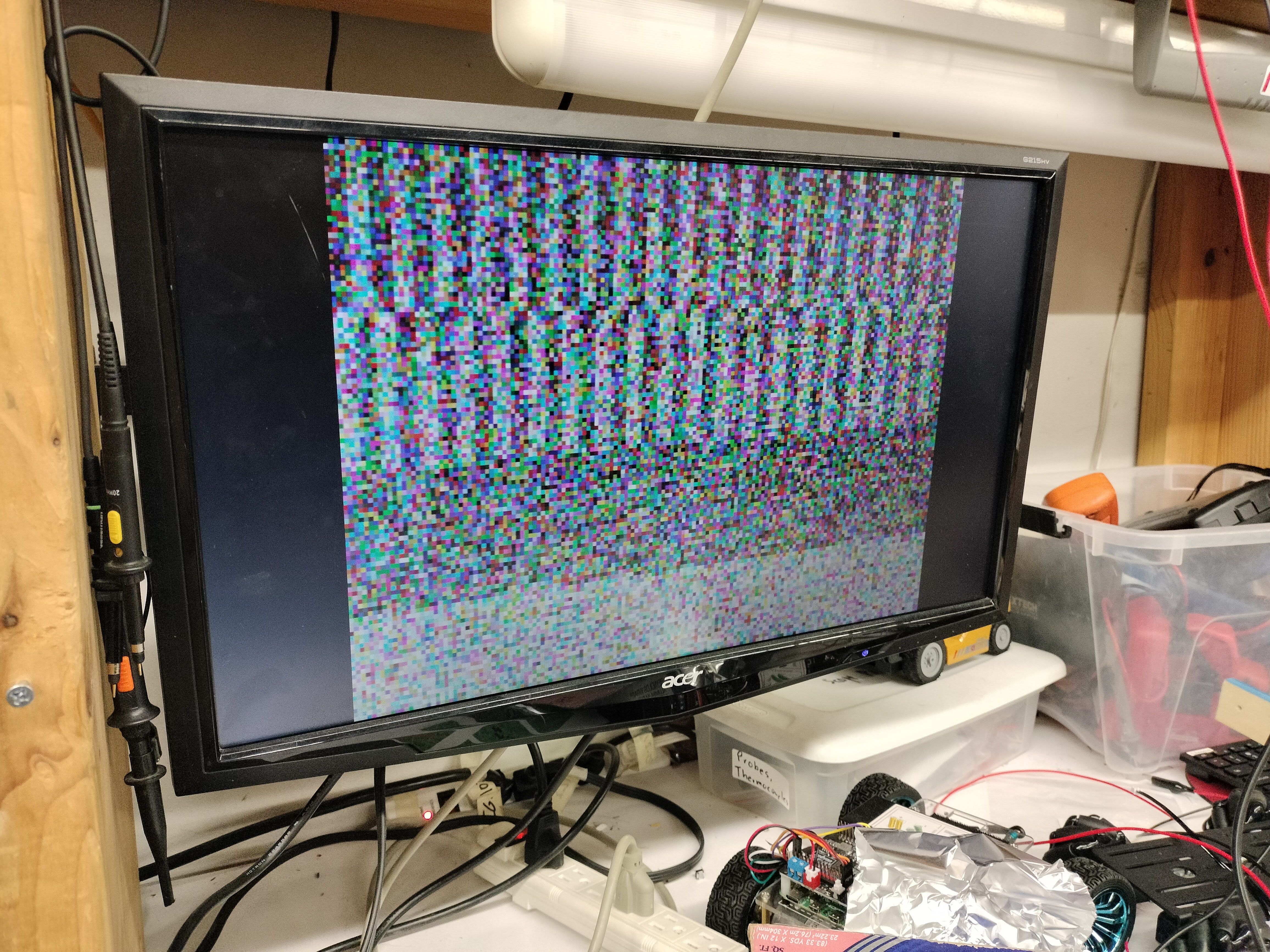
You might be a bit surprised at the fact that I describe this above image as "working" but it is - when the framebuffer starts up, all of the pixels are in an unspecified state. In this case, they seem to have settled a little bit into a pattern based on the address bits - interesting.
I unfortunately don’t have a super cool demo to show for the video adapter, but here’s at least an animation of a box moving across the screen in real time :3